Wiring a seven segment display can be a bit confusing, this guide aims to be a practical guide to get you started.
A seven segement display is basicly just a bunch of LED's wired together in one easy to use package. Some displays have a DP (dotted point) and some don't, check the datasheet to know which one you're getting.
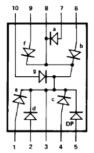
We start by determining if our 7 segment display component has a common cathode (negative side) or anode (positive side). To determine this you search the part number online and check the datasheet. In our case (a HDSP-5503) the part has a comon cathode. In most datasheets this is mentioned in the text, if it isn't you can easily determine this yourself by looking at the internal wiring schematic of the part (see image below) where the LED's are shown with their polarity, the direction the schematic symbol arrow is pointing to is the cathode (negative) side, the other side is the anode (positive) side. We can also see in the datasheet that the common ground is located at Pin 3 and Pin 8. These are the only 2 pins were all the LED's are connected to.
Our seven segment display will need resistors at each leg to prevent the LED's from drawing to much current. Our datasheet tells us each LED has a maximum forward voltage of 20mA, so we use a little less to save the LED a bit, we're picking 12.5mA. Using Ohms Law we can easily determine the resistance needed.
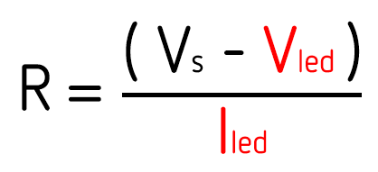
R = the resistance we want to calculate
Vs = the source voltage (we are picking 3.3V)
Vled = the voltage drop across our LED (our datasheet tells us 1.8V)
Iled = the current through the resistor (we're picking 12.5mA)
so in our case the result is 120Ω (Ohm)
We need to put a resistor at each pin of this value to prevent the LED's from blowing up. If we would only put 1 resistor at the common pin for example the LED's would get different amounts of current for every digit you're trying to display, if you would only display the same digit every time you can get away by calculating the total current resistor value but because each LED in our case is individually addressable we need to put a resistor at each of them.
To create your digits we simply map the corresponding LEDs to a byte. If we want the top LED bar of our segment to light up we first find out which port number is attached, lets say the top bar is connected to the 4th pin our our shift register we can write this in byte as: 00010000, to use it with an arduino we can easily reference our digits using a dictionary like this:
byte one = 0b00010010;
 byte two = 0b01100111;
 byte three = 0b01110110;
 byte four = 0b11010010;
 byte five = 0b11110100;
 byte six = 0b11110101;
 byte seven = 0b00010110;
 byte eight = 0b11110111;
 byte nine = 0b11110110;
 byte zero = 0b10110111;
 byte test = 0b10000000;
 byte empty = 0b00000000;
 byte numbers[] = {zero,one,two,three,four,five,six,seven,eight,nine};
Referencing a digit is as simple as: numbers[6] (in this example we're referencing the digit 6)